Difference between revisions of "MSI Protocol"
(→Cache Controller) |
(→Directory Controller) |
||
| Line 74: | Line 74: | ||
The directory tracks all block states of the L2 currently in use, so those that are in the state I, S or M. In the following figure it is reported the finite state machine of the DC in table form: | The directory tracks all block states of the L2 currently in use, so those that are in the state I, S or M. In the following figure it is reported the finite state machine of the DC in table form: | ||
| − | [[File:MSI_Protocol_dc- | + | [[File:MSI_Protocol_dc-rom_new.png]] |
Note that, as before, all the states and messages that are not reported in the ''Primer''<ref name=primer /> are marked in light blue. The chosen notation for the directory is cache-centric, so the state of a directory entry is given by the state of the block in the other cache controllers. In particular, these are the states for a block into the DC: | Note that, as before, all the states and messages that are not reported in the ''Primer''<ref name=primer /> are marked in light blue. The chosen notation for the directory is cache-centric, so the state of a directory entry is given by the state of the block in the other cache controllers. In particular, these are the states for a block into the DC: | ||
Revision as of 16:57, 20 June 2019
The NPU coherence subsystem is based on a sparse directory approach, featuring a private L1 cache embed at the core level and an L2 cache shared among all cores.
This protocol is based on the directory-MSI depicted in A primer on memory consistency and cache coherence[1], with two main differences:
- The directory is not centralized into a particular tile of the NoC, but it is distributed among all tiles;
- Directory’s L2 memory is limited.
In the details of the protocol we refer to three different entities: Cache Controller (CC), Directory Controller (DC) and Memory Controller (MC).
Contents
Cache Controller
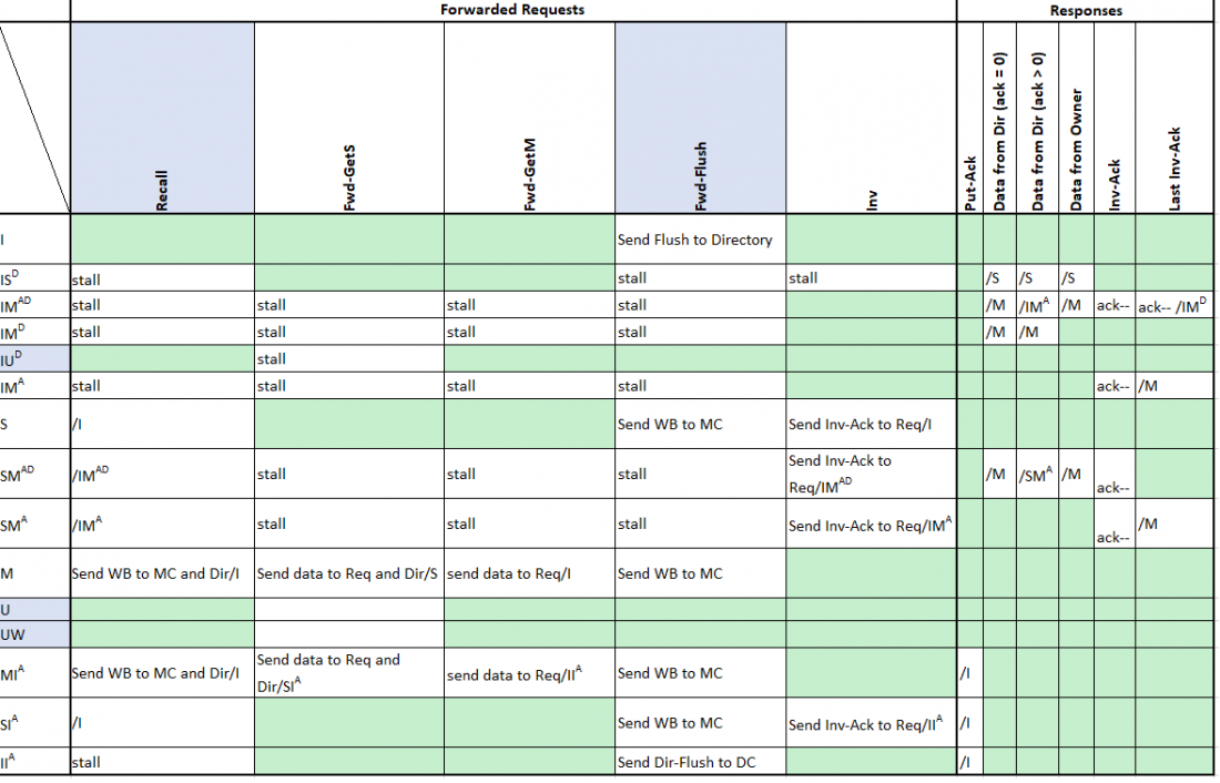
The algorithm for CC is implemented as a finite state machine, that is reported in the following figure in a table form:
Note that we report in light blue all states and messages that differ from the Primer[1]. In particular, we use the following 4 stable states:
- Modified – The owner of the block is the cache controller and it has the most recent copy of the data.
- Shared – Cache controller holds the block in read-only privilege.
- Invalid – The block is not up to date.
- Uncoherent – The block is managed from the cache controller bypassing the coherence maintanance, like it was the only actor to access to the block.
The presence of U state is an optimization which allows the user to handle a cache block like it was private. Such a mechanism defines non-coherent regions where coherence maintenance is bypassed for a given class of data. A realistic case is the one in which a core produces (private) data that should be inaccessible to others. Moreover, coherence maintenance for specific memory regions, such as threads stack or memory instructions, causes performance loss due to false sharing. In such contexts, managing coherence results in a system overhead with no benefits: non-coherence regions overcome these unnecessary transactions typical of those scenarios, avoiding counter-producing overheads resulting in an improvement of efficiency. It is necessary, however, to track all the changes of a non-coherent block when the core needs to evict the block to LLC.
For this reason, another state has been added: UW reports that a block is in a non-coherent state and the core tried to write on it.
The followings are the messages that a CC can produce/receive:
- Load – Load-Store Unit produces this message when it wants to read a cache block;
- Store – Load-Store Unit produces this message when it wants to write a cache block;
- Replacement – Message which triggers the eviction of the block to the directory;
- Fwd-GetS – Message received from another tile that has request a GetS for the block;
- Fwd-GetM – Message received from another tile that has requested a GetM for the block;
- Inv – Message which forces the invalidation of the block;
- Put-Ack – Message which notifies the CC that the eviction of a block has been completed;
- Data from directory (ack count = 0) – Data received from directory along with associated ack-count equals to 0;
- Data from the directory (ack count > 0) – Data received from directory along with associated ack-count greater than 0;
- Data from owner – Data received from another CC or from the LLC;
- Inv-Ack – Message that is generated after an invalidation request from another tile;
- Last Inv-Ack – The last Inv-Ack that the CC was waiting for;
- Load-uncoherent – The uncoherent version of the load;
- Store-uncoherent – The uncoherent version of the store;
- Replacement-uncoherent – The uncoherent version of the replacement;
- Flush – Message which forces a writeback on LLC, without transitioning into I state;
- Flush-uncoherent – The uncoherent version of the flush;
- Dinv – Request from the core which forces the invalidation of the block;
- Dinv-uncoherent – The uncoherent version of the Dinv;
- Recall – Message sent from DC to CC in order to keep valid the invariance of L2-cache inclusivity;
- Fwd-Flush – Message received from the CC, which forces it to write the current data back to LLC.
Uncoherent transactions
To better understand the optimization offered by the U/UW states, it can be interesting going in deep into some key scenarios of non-coherent access to a cache-block. In particular, we will analyse three different cases: in the first one the core wants to non-coherently read a block, in the second one it wants to non-coherently store a block (or a part of it), in the third one it wants to load a block that it previously stored in a non-coherent way.
Load
Suppose to have a block in state I and to submit to CC a load-uncoherent instruction. Even if in uncoherent mode, the core wants to read the up-to-date value, so it first has to fetch the data. Then, it sends an Fwd-GetS to MC and sets its state to IUD, waiting for a “Data from Owner” message (in this context the owner is the LLC). When the data arrives, the CC transits into U stable state. Other load-uncoherent instructions produce a cache hit as a result.
Store
Suppose to have a block in the state I and to submit to CC a store-uncoherent instruction. Being a store, the CC does not have to fetch the data, but it can start to write immediately (in fact a store-uncoherent over an I state produces a cache-hit as result). After that, it transits into UW stable state. At the moment of a write operation, the CC updates a dedicated structure called Dirty Mask, organized as a bitmap in which every bit represents if the corresponding byte is clean or not. Other store-uncoherent instructions produce a cache hit and an update of the Dirty Mask as a result.
Load after Store
Suppose to have a block in UW, the result of a previous store-uncoherent instruction. In UW state the CC has requested to write on a cache line partially or totally without fetching the data from memory first, consequently a load-uncoherent operation could produce a read of an expired value. Here comes the utility of the Dirty Mask: if the load-uncoherent is requested on a dirty byte, then it produces a cache-hit, otherwise, if the byte is clean, the value is considered as expired and an Fwd-GetM is issued to MC. This GetM, however, will overwrite only the clean bytes and the data stored as non-coherent will remain as it is.
Limited directory memory
The number of the entries that a directory controller can handle is assumed limited and, being M the number of available locations, the following relation is constantly valid:
<math>M_{dir}<\sum_{i=1}^Template:NUM\ CORE { M_{cache_{i}} }\!</math>
It is realistic a case in which a directory entry has to be replaced. Due to the invariance of L2-cache inclusivity, a mechanism to “recall” L2 blocks is needed. In other words, the directory needs to force the invalidation of any L2 cache block. This mechanism is given by the Recall message which is sent by DC and received by the CC.
Directory Controller
The directory tracks all block states of the L2 currently in use, so those that are in the state I, S or M. In the following figure it is reported the finite state machine of the DC in table form:
Note that, as before, all the states and messages that are not reported in the Primer[1] are marked in light blue. The chosen notation for the directory is cache-centric, so the state of a directory entry is given by the state of the block in the other cache controllers. In particular, these are the states for a block into the DC:
- Modified – The owner of the block is a CC and it has the most up-to-date value. In other words, this CC has the block in M state, all the others have the block in I.
- Shared – The block is in read-only state at some CCs and both the CCs and the DC have the up-to-date value. In other words, it exists a subset of CCs that has the block in state S, all the others have the block in state I, but no one has the block in M.
- Invalid – The block is in the state I at all CC of the system and the DC has the up-to-date value. This value is not aligned with the LLC, which has a previous version of it.
- Non-cached – The block is not present at the directory level (and hence, for the inclusivity, in no L1 cache, too). In this case the owner is the MC and the most up-to-date value is into the LLC.
Differently, from the Primer[1] the state N has been introduced. Due to the limited memory of the directory, it is needed to manage a new set of possible cases, in which the directory does not have any information about the block requested by a CC and has to forward the request to the off-chip memory.
Note that the Replacement message is not a request from a core, but a message auto-generated from the DC itself, in case it needs to replace an entry. This is directly related to the relax of the constraint (b).
Transitions of state N
It is clear that for the DC are particularly interesting the transitions from and to stable state N. So in the following, these two cases will be analysed:
- Transition from N to S
- Transition from M to N
In the first case, suppose to have a block in state N and to have a core requesting GetS: first, the DC will add the requestor to the list of the sharers; second, since the DC does not hold the block, an Fwd-GetS will be issued to MC. At this point, the DC will transit to NSD, in which waits for the DATA message. When the data arrives, the DC can transit to the stable state S.
In the second case, suppose to have a block in state M that should be replaced, because of the generation of a Replacement message from the DC: due the state of the block, the DC knows that the up-to-date value is currently held by the owner (that in this context is the CC), hence it sends a Recall message to that CC. This triggers a writeback to LLC. After that, the DC transits to the state MNA, waiting for the LLC to complete the transaction. This transaction is notified by a message of MC_Ack, whose arrival determinates the transition of the DC into the stable state N.
The key role of MC_Ack
The presence of MC_Ack is necessary to handle the transitory between the sending of a Recall to the owner and the commit of the memory to write that particular value (that represents the most up-to-date value). Without MC_Ack, in fact, the DC would transit from M to N directly, becoming available to other read or write requests. Consider the following example, made by a linearization of events on two CC and the DC, that proves that without MC_Ack there would be a violation of the correctness of the algorithm:
- DC generates an event of REPLACEMENT;
- DC sends a RECALL message to the owner CC1;
- DC transits to N;
- CC1 receives a RECALL and sends the up-to-date value to LLC;
- CC2 requests a load of the block, that is (for it) in state I;
- CC2 sends a GetS to DC;
- DC sends a Fwd-GetS to the LLC;
- MC receives an Fwd-GetS (but it has not received the DATA from CC1);
- MC responds to DC with a non-up-to-date value.
Introducing the MC_Ack, the DC stalls at point 7 and it will be woken up after the DATA from CC1 has been written in LLC.
Remarks
The coherence protocol is shaped considering specific design choices, that aim to overcome possible race conditions introduced by the finite directory and the state N. It is interesting going in deep into two key scenarios of race conditions.
- Suppose CC is in S and it sends a PutS to DC. Then, it turns into SI_A, waiting for Put-Ack. Before receiving PutS, DC (S state) sends a WB to MC due an event of replacement, turning its state into SN_A. When DC receives MC_Ack form MC, DC transits to state N. A naive version of the protocol required no action at DC level when a PutS is received, and at this point the CC would be stalled forever waiting for a Put-Ack not generated at all. In order to overcome this condition, a DC in N state replies with a Put-Ack after a PutS/M, in order to allow the CC to come out from the stalling state.
- Suppose CC is in M and it sends a PutM to DC. Then, CC turns into MI_A. Before receiving PutM, DC (M state) sends a recall to CC because of an event of replacement, turning into MN_A. Then, when the DC receives the PutM, it responds with a Put-Ack to CC. As soon as the CC receives the Put-Ack, it turns into I stable state. Then, the CC receives the DC's recall message, producing no actions. A problem arises because nobody will send WB to MC, stalling DC which is waiting for a MC_ACK: in the naive version of the protocol the DC assumes that WB would be sent by CC after the recall reception. In such a scenario, not the CC, nor the DC, send a WB to the LLC. So, the proposed solution is to assign DC to send WB to MC, since the ownership of the data is back to the directory after a PutM. DC replies with a Put-Ack, but it cannot send two messages of the same type (response in such a case) at the same time due design limitations. Then, the DC stalls the pipe and resolves this structural conflict sending the second response in the following cycle, storing the outgoing response in a dedicated FIFO.
Memory Controller
We assume to have an extremely simple (for what concerns the memory coherence protocol) MC, in fact it can receive only messages of type Forward or Response (see message's level section for the type of the messages). In particular, the following figure report the finite state machine of the MC in table form:
Note the event of generation of an MC_Ack: it comes when the memory receives a message of type WB, which represents the willing of DC or CC to update a value in LLC.
Messages level
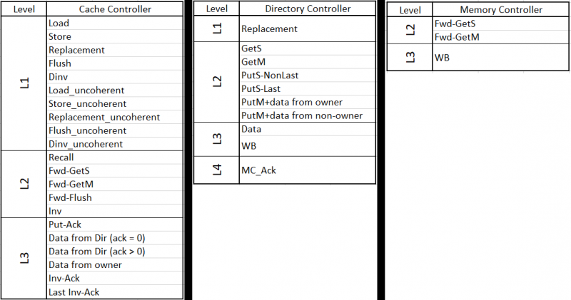
MSI Protocol leverages on hardware messages, that are classified in four different levels.
First, we have Request messages, generated directly from one of the actors and are driven by a system/user event, so they are not triggered by the arrival of other coherence messages. From the CC point of view, Load-Store messages are part of this class, so load, store, flush, dinv, replacement and their uncoherent version; while for DC the Replacement message is part of this class.
Next, we have Forward messages, that might be generated from the arrival of a Request. Messages that come from the network are part of this class: for CC, Recall, Fwd-GetS, Fwd-GetM, Fwd-Flush, Inv; for DC, GetS, GetM, PutS, PutM; for MC, Fwd-GetS, Fwd-GetM.
Then, we have Response messages, that are generated as an answer to Request or Forward messages, so still coming from the network. For CC, Put-Ack, Data and Inv-Ack; for DC and MC, DATA and WB;
Finally, the fourth class of messages exists, that is composed of only a message, namely the MC_Ack message. It is generated by the MC after a WB (i.e. a Response message), hence MC_Ack lies in a lower level than a Response.
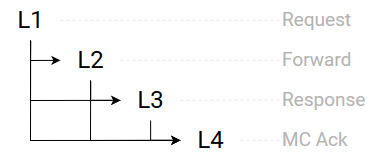
An important property that is always guaranteed and helps for the study of lockings of the protocol is this invariant:
“A message of level i can generate messages of level greater than i and cannot generate messages of a level lower or equal to i”
where we can label Requests, Forwards, Responses, MC_Acks, respectively as L1, L2, L3, L4.
The next figures show the trigger effect that a message class can cause to another class and the division of every message of each actor into classes.
Attachments:
References:


