Difference between revisions of "Core"
(→Integer Arithmetic & Logic unit) |
(→Barrier unit) |
||
| Line 33: | Line 33: | ||
== Barrier unit == | == Barrier unit == | ||
| + | |||
| + | Daniele | ||
== Scratchpad unit == | == Scratchpad unit == | ||
Revision as of 18:21, 20 September 2017
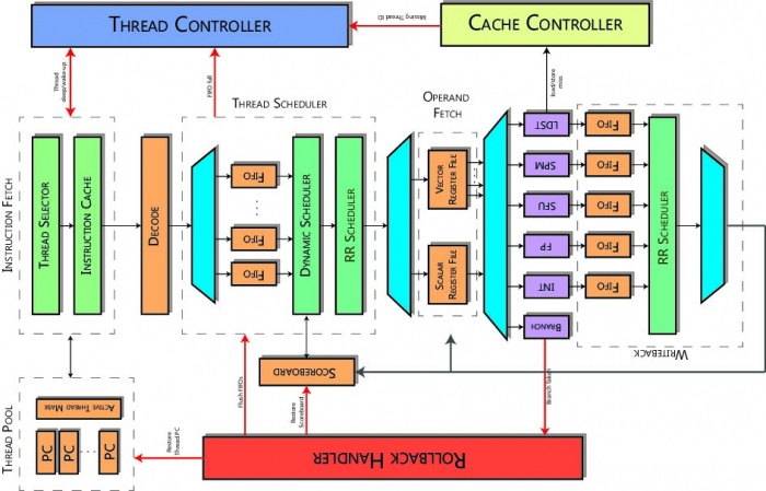
The core is based on a RISC in-order pipeline. Its control unit is intentionally kept lightweight. The architecture masks memory and operation latencies by heavily relying on hardware multithreading. By ensuring a light control logic, the core can devote most of its resources for accelerating computing in highly data-parallel kernels. In the hardware multithreading nuplus architecture, each hardware thread has its own PC, register file, and control registers. The number of threads is user configurable. A nuplus hardware thread is equivalent to a wavefront in the AMD terminology and a CUDA warp in the NVIDIA terminology. The processor uses a deep pipeline to improve clock speed.
All threads share the same compute units. Execution pipelines are organized in hardware vector lanes (like vector processors, each operator is replicated N times). Each thread can perform a SIMD operation on independent data, while data are organized in a vector register file. The core supports a high-throughput non-coherent scratchpad memory, or SPM (corresponding to the shared memory in the NVIDIA terminology). The SPM is divided in a parameterized number of banks based on a user-configurable mapping function. The memory controller resolves bank collisions at run-time ensuring a correct execution of SPM accesses from concurrent threads. Coherence mechanisms incur a high latency and are not strictly necessary for many applications.
Contents
Instruction fetch stage
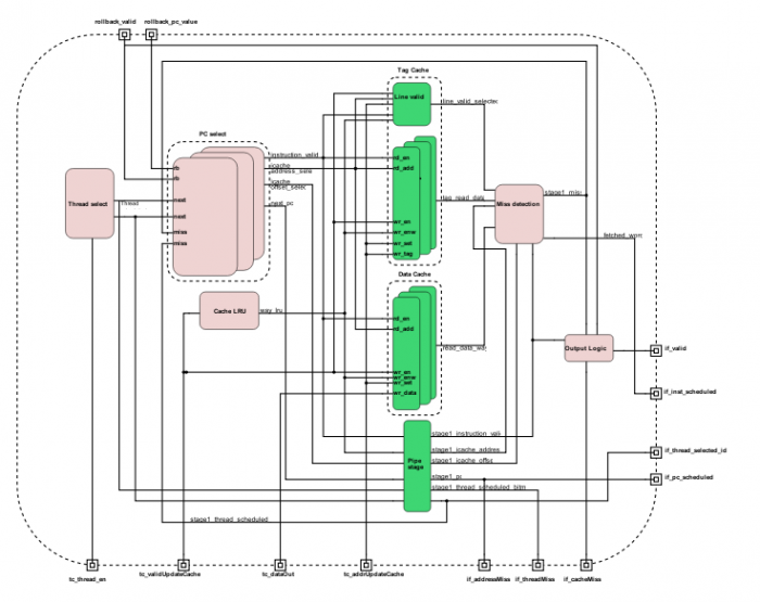
Instruction Fetch stage schedules the next thread PC from the eligible thread pool, handled by the Thread Controller. Available threads are scheduled in a Round Robin fashion. Furthermore, at the boot phase, the Thread Controller can initialize each thread PC through a specific interface.
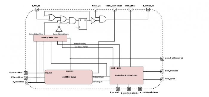
The instruction cache is set associative and has two stages. Once an eligible thread is selected, Instruction Fetch reads its PC, and determines if the next instruction cache line is already in instruction cache memory or not. In the first stage each way has a bank of memory containing tag values and valid bits for the cache sets. This stage reads the way memories in parallel and passes those data to the second stage. The next stage tag memory has one cycle of latency, so the next stage handles the result. This stage compares the way tags read in the last stage, if they match, it is a cache hit. In this case, this stage issues the instruction cache data address to instruction cache data memory. If a miss occurs an instruction memory transaction is issued to the Network Interface and the thread is blocked until the instruction line is not retrieved from main memory.
Finally, this module handles the PC restoring in case of rollback. When a rollback occurs and the rollback signals are set by Rollback Handler stage, the Instruction Fetch module overwrites the PC of the thread that issued the rollback.
Decode stage
Decode stage decodes fetched instruction from Instruction Fetch and produces the control signals for the datapath directly from the instruction bits. Output dec_instr helps execution and control modules to manage the issued instruction and is propagated in each pipeline stage. Instruction type are presented in the ISA section.
Instruction scheduler stage
Fetched instructions are stored in FIFOs in this stage, one per thread. The Dynamic Scheduler checks data hazard and states which thread can be fetched in the Operand Fetch; this is done through a light scoreboarding system, each thread has its own scoreboard. There are no structural hazard check, it is done in Writeback stage.
Operand fetch stage
Operand Fetch prepares operands to the Execution pipeline. As said before, nu+ core supports SIMD operations, for this purpose it has two register files: a scalar register file (SRF) and a vector register file (VRF). The SRF is general purpose register and in the base configuration it has 64 registers of 32-bits. Dually, the VRF register size has a scalar register file for each hardware lane, in other word each vector register is composed by hardware lane number of scalar register; in the base configuration the VRF has 64 vector registers and each vector register is composed of $16$ scalar register of 32-bits. Each thread has its own register file.
Integer Arithmetic & Logic unit
A single stage executes simple integer instructions, as integer operations, comparisons and bitwise logical operations.
Barrier unit
Daniele
Scratchpad unit
This unit is described in the dedicated scratchpad page.
Load/Store unit
This unit is described in the dedicated load/store subsection inside the coherence section.
Floating point unit
Barrier unit
This unit is described in the dedicated synchronization section.


